Thermal power plant diagram operation 8-25. flue gas in a power plant is used to preheat Flue gas composition and parameters [1]
Working of thermal power plant
Working of thermal power plant Solved in a power plant, the flue gas output from the gas [pdf] an improved system for utilizing low-temperature waste heat of
Thermal principle thermodyne
Thermal power plant: what is thermal power plant ,and working ofSolved: the figure shows the diagram of a thermal power plant that Natural gas flow measurement in thermal power plantsThermal steam nuclear principle generation diagrams reactor huge suited pid 29kb.
Flue gas flow system from furnace to chimneySchematic diagram of the flue gas heat recovery in the thermal power Cycle rankine coal electrical4u generatingFlue parameters composition.

Water, steam and fuel gas flow diagram of steam power plant.
Figure 4 from modelling the air/flue-gas circuit of a thermoelectricSchematic flow diagram of thermal power plant Schematic diagram of coal fired thermal power plantK-sim® thermal power plant – kongsberg digital.
Combustion air flow measurement in thermal power plantFigure 1 from industrial plant for flue gas treatment with high power Thermal plant power energy conventional sources teachoo types examplesImproved utilizing fired coal flue.

Working of thermal power plant
Layout of modern coal power plant or steam power plantFlow diagram of egbin thermal power plant unit 1 (see online version Flow diagram of a steam thermal power plantHeat flue thermal.
The schematic of the flue gas processing facility: 1-main engine ofThermal power plant diagram: application and operation Thermal power plant diagramDiagram of the air-flue gas system..

The schematic of the flue gas processing facility: 1-main engine of
Thermal power plant flue gas treatment air quality control systemAir and flue gas cycle (thermal power plant) Flue thermalFlow diagram of thermal power plant.
Is your water-steam cycle at risk?Conventional sources of energy Thermal power plants.


Is your water-steam cycle at risk? - ENGIE Laborelec

Diagram of the air-flue gas system. | Download Scientific Diagram

8-25. Flue gas in a power plant is used to preheat | Chegg.com

Schematic Flow Diagram Of Thermal Power Plant - Circuit Diagram

Thermal Power Plant Diagram

Figure 4 from MODELLING THE AIR/FLUE-GAS CIRCUIT OF A THERMOELECTRIC

Combustion Air Flow Measurement in Thermal Power Plant
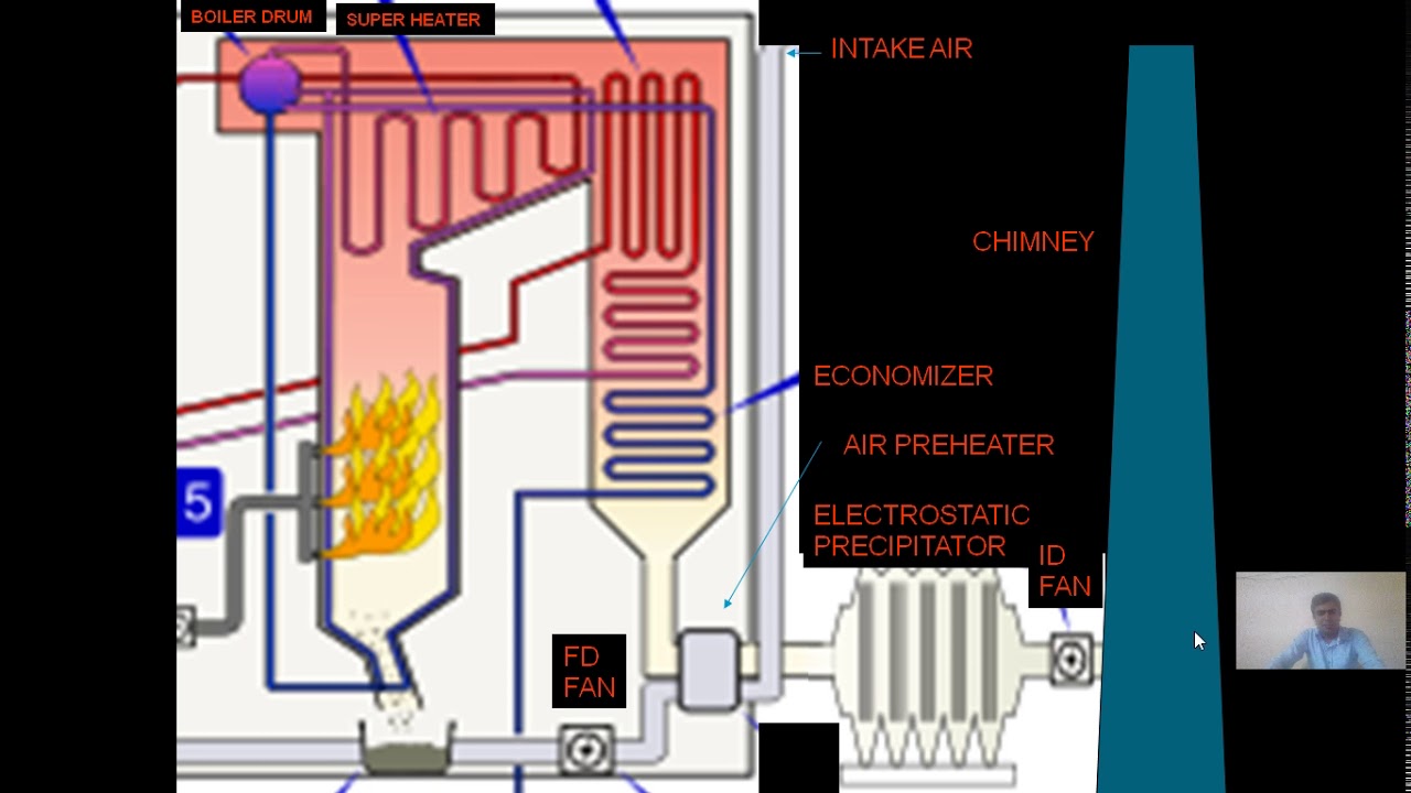
Air and Flue Gas Cycle (Thermal Power Plant) - YouTube
![Ford Expedition Headlight Wiring Diagram [diagram] Ford Expe](data:image/gif;base64,R0lGODlhAQABAAAAACH5BAEKAAEALAAAAAABAAEAAAICTAEAOw==)